Sensor Watch Accessory Boards (aka Sensor Boards)
You may have noticed that there are no sensors on this board. That is by design: rather than pick sensors for you, the goal is to add a tiny flexible PCB with the sensors YOU want, and interface them over the nine-pin connector. The connector provides the following options for power and connectivity:
- 3V power (nominal voltage from a CR2016 coin cell, can drop to ~2.7V)
- An I²C interface with built-in pull-up resistors
- Five general purpose IO pins, which can be configured as:
- Five analog inputs
- Five interrupt-capable digital inputs, with internal pull-up or pull-down resistors
- Five digital outputs
- SPI controller (with one spare analog / GPIO pin leftover)
- One UART TX/RX pair (with three GPIO leftover)
- Up to four PWM pins on two independent TC instances
- Two external wake inputs that can wake from the ultra-low-power BACKUP mode
| Pin | Digital | Interrupt | Analog | I2C | SPI | UART | PWM | Ext. Wake |
|---|---|---|---|---|---|---|---|---|
| A0 | PB04 | EIC/EXTINT[4] | ADC/AIN[12] | — | — | — | — | — |
| SCL | — | — | — | SCL SERCOM1[1] | — | — | — | — |
| SDA | — | — | — | SDA SERCOM1[0] | — | — | — | — |
| A1 | PB01 | EIC/EXTINT[1] | ADC/AIN[9] | — | SCK SERCOM3[3] | RX SERCOM3[3] | TC3[1] | — |
| A2 | PB02 | EIC/EXTINT[2] | ADC/AIN[10] | — | MOSI SERCOM3[0] | TX or RX SERCOM3[0] | TC2[0] | RTC/IN[1] |
| A3 | PB03 | EIC/EXTINT[3] | ADC/AIN[11] | — | CS SERCOM3[1] | RX SERCOM3[1] | TC2[1] | — |
| A4 | PB00 | EIC/EXTINT[0] | ADC/AIN[8] | — | MISO SERCOM3[2] | TX or RX SERCOM3[2] | TC3[0] | RTC/IN[0] |
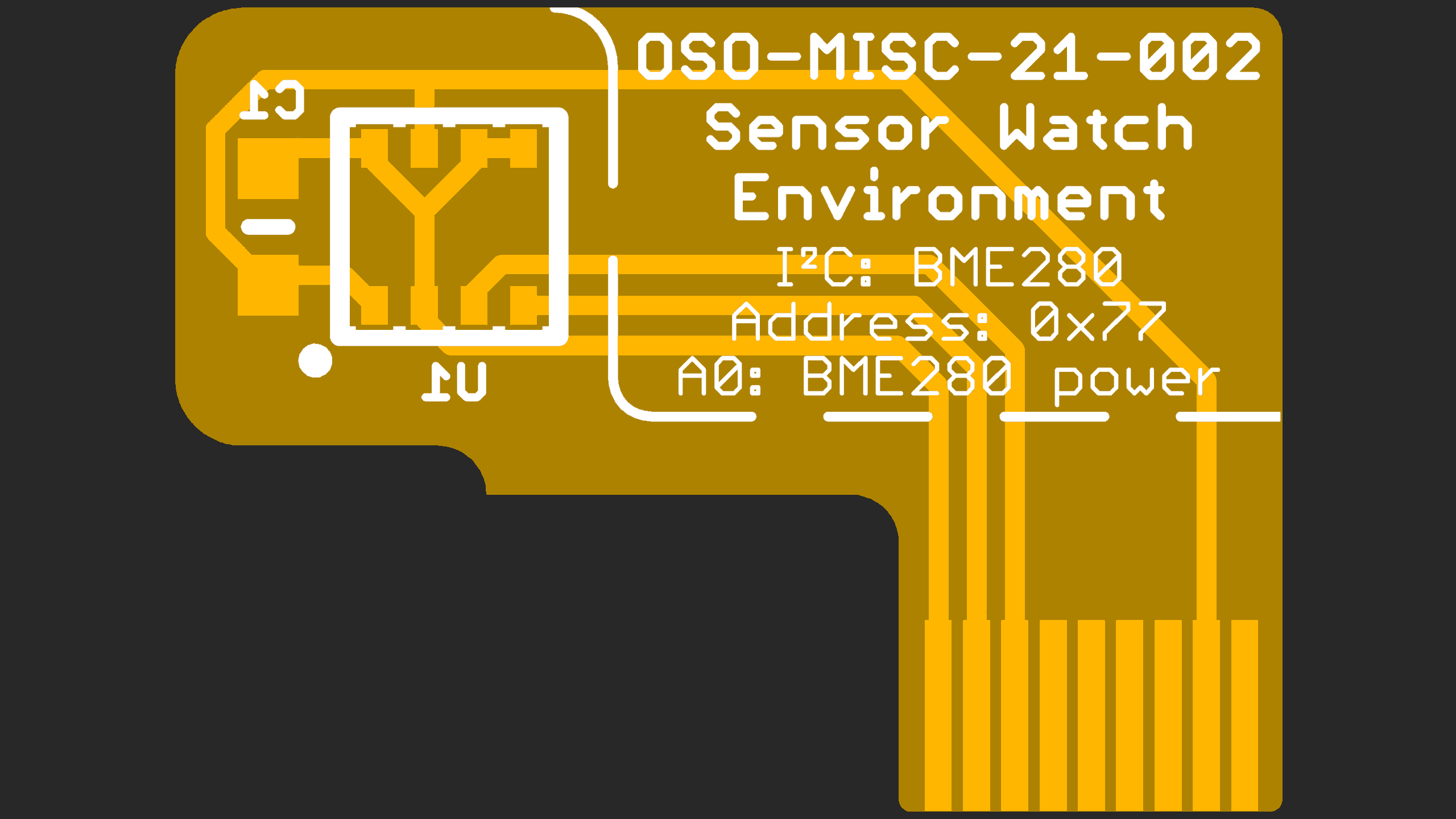
These tiny “sensor boards” have a set outline, and the available area for your electronics is quite small (5.7 × 5.7 × 1 mm). Still, this is plenty of room for an environmental sensor, MEMS accelerometer or magnetometer and a couple of decoupling capacitors. Note that you will likely be limited to QFN and LGA type parts; SOICs are too large, and even SSOP packages are generally too thick. You can find reference designs for several sensor boards in the PCB/Sensor Boards directory in the Sensor Watch repository.